Lamination of printed circuit boards
Back to EFFICIENCY FINDER FOR METAL INDUSTRY
Lamination
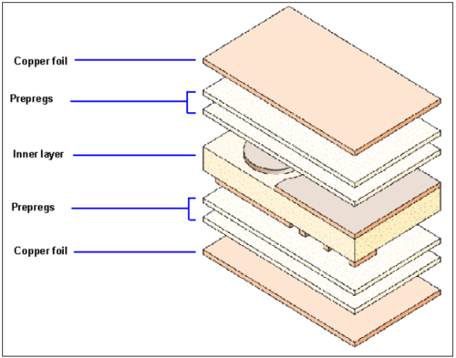
Both the laminates and the insulating layers (the prepregs) have to be bonded strongly and using oxidised copper surfaces prevents delamination of the finished board. The pre-oxidised cores of the multilayer are laminated with bonding sheets (prepregs) and copper foils (outer layers), see Figure 1.
The prepregs are shaped sheets of pre-polymerised epoxy resin reinforced with glass fibre. They liquefy under the influence of pressure and temperature and bond with the inner cores.
Figure 1: Schematic of a multilayer board
The principal working steps for the lamination process are:
- lay up (registration) in the lay-up station
- lamination in a vacuum press
- destacking of the lamination tool
- trimming of the flash on the rim of the MLB.
Environmental considerations
Offcuts from laminating and trimming can be recycled to recover the metals via specialist companies.
Inner layer bonding adhesion
Oxide processes have been commonly used and are described below. However, other processes are now emerging (sometimes referred to as oxide alternative treatments). One type creates a copper azole complex at the surface. Developments of these processes are rapid and driven by ever-increasing higher technical requirements [159, TWG, 2004].
The copper surface on inner layers is oxidised to Cu(I) to improve the adhesion between cores and prepregs and to prevent subsequent delamination (separation of multilayer boards). The oxide layer of 0.5 – 5 ^m is formed by one of two processes:
- the brown oxide process is most commonly used and consists of hydrogen peroxide,
organic additives (for passivation) and chloride (in mg quantities only), running at 30 °C
- the black oxide process is carried out in a solution of sodium phosphate (Na3PO4),
sodium hydroxide (NaOH), and sodium chlorate (NaClO2) or hypochlorite (NaOCl) at 80 °C.
Effluents can be minimised by ensuring the concentration of the individual components is
maintained by additions equalling the evaporation rate.
Thorough rinsing is necessary after the process.
Environmental considerations
The brown oxide process is increasingly used as it runs at lower temperatures and does not use chlorate or hypochlorite.
The process may need air extraction.
Effluents can be minimised and treated in a typical waste water treatment plant. A new bath is made up at approximately 24 months intervals, and can be discarded after batch treatment by alkaline precipitation.
Oxide alternative treatments reduce consumptions of chemicals and water and generation of waste.
Typical process parameters
| Process | Temperature [°C] | Heat transfer medium | Residence time | Details | Literature |
| Pressing | 170-215 °C | continious | multi-layer PCB | Risse, A. (2012). Leiterplattentechnologie. In Fertigungsverfahren der Mechatronik, Feinwerk- und Präzisionsgerätetechnik. Springer Berlin Heidelberg. |
Source: European Commission, Reference Document on Best Available Techniques for the Surface Treatment of Metals and Plastics, August 2006
