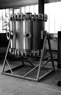
Distillation with heat integration
Back to EFFICENCY FINDER OF FOOD INDUSTRY
GENERAL INFORMATION
Heat recovery in distillation can be performed with absorption heat pumps and heat transformers. Most common heat exchangers are shell-and-tube heat exchanger or spiral heat exchangers.
TECHNOLOGY DESCRIPTION, TECHNIQUES AND METHODS
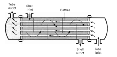
Shell and tube heat exchangers
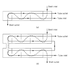
The shell and tube heat exchangers is configured as a bundle of tubes inside a shell. Specific forms differ according to the number of shell and tubes passes. Baffles are installed inside the shell to increase the convection coefficient and improve the heat transfer between fluids. The tubes are supported by the baffles and this way vibration due to the fluid circulation is reduced.
Illustration 1: Shell and tubes heat exchanger [1]
The shell construction allows this heat exchanger to be suited for higher-pressure applications. One fluids runs along the tubes and the other fluid runs over the tubes, conducted by the baffles and increasing the heat convection. The cross section of the inner tubes is rounded and the geometrical construction characteristics depends on the requirements of the heat exchange (pressure, temperature, flow rate, fluid, etc.)
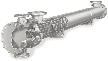
Some configurations of the shell and tube heat exchanger are shown below:
Illustration 2: Shell and tubes heat exchanger [2]
Illustration 3: Shell and tubes heat exchanger [3]
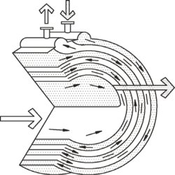
Spiral heat exchangers
Spiral HX is used as an alternative to shell and tube exchangers where low maintenance is required, particulary with fluids tending to sludge or containing slurries o solids in suspension. The advantages of using a spiral HE is precisely to handle with slurries and liquids with suspended fibers where the solid content is up to 50%. This exchanger is the first choice for extremely high viscosities, especially in cooling processes. The mains applications for the spiral HE are finding in reboiling, condensing, heating and cooling viscous fluids, slurries and sludge.
The fluids flow can be parallel, counterflow, crossflow, or a combination of these. Its thermal effectiveness is about 98% in a single unit.
A spiral plate heat exchanger is fabricated by rolling a pair of relatively long strips of plate to form a pair of spiral passages. Channel spacing is maintained uniformly along the length of the spiral passages by means of spacer studs welded to the plate strips prior to rolling. It can be made with channels 5–25 mm wide, with or without studs. The spiral channels are welded shut on their ends.
in order to contain respective fluids. An overall gasket is applied to the cover. The covers are attached to the spiral element by means of forged hook bolts and adapters. The hook bolt engages the bevel at the back of the flange ring and the adapter engages the rim at the edge of the cover. A header is welded on the outer end of each passage to accommodate the respective peripheral nozzle. For most services, both fluid flow channels are closed by alternate channels welded at both sides of the spiral plate. In some applications, one of the channels is left completely open, and the other closed at both sides of the plate. These two types of construction prevent the fluids from mixing.
The spiral assembly can be fitted with covers to provide three flow patterns types:
- Both fluids in spiral flows; this arrangement can accommodate the media in full counter-flow. General uses are for liquid to liquid, condensers, and gas coolers.
- One fluid in spiral flow and the other in axial flow across the spiral; general uses are as condensers, reboilers, and gas coolers and heaters.
- One fluid in spiral flow and the other in a combination of axial and spiral flow; general uses are as condensers (with built-in aftercoolers) and vaporizers.
Advantages
- The spiral heat exchanger approaches the ideal in heat exchanger design. Media can be arranged in full counterflow. Flow characteristics are the same for each medium. The long passages on each side permit close temperature approaches. Radiation losses are negligible.
- The exchanger is well suited for heating or cooling viscous fluids because its L/D ratio is lower than that of tubular exchangers.
- At a velocity that would be marginal and approaching streamline flow in straight tubes, good turbulence is realized because of the continuously curving passages.
- The scrubbing action of the fluids in each side of the passage tends to flush away deposits as they form and hence permits the use of low fouling resistance values.
- Media cannot intermix; they are isolated by the welded closing on one side of each passage.
- The spiral exchanger is compact and requires less installation and servicing space than conventional exchangers of equivalent surface.
- They are easily maintainable. By removing the covers of the spiral exchanger, the entire lengths of the passages are easily accessible for inspection or mechanical cleaning, if nec-essary. Similarly, because of the single passage on each side, the spiral heat exchanger is readily cleaned with cleaning solutions without opening the unit.
- Spiral plate exchangers avoid problems associated with differential thermal expansion in non-cyclic service.
- In axial flow, a large flow area affords a low pressure drop, which becomes especially important when condensing under vacuum.
Limitations
- Repairing an spiral heat exchanger in the field is difficult; however, the possibility of leakage in a spiral is less because it is generally fabricated from much thicker plate than tube walls.
- Spiral plate exchangers are not recommended for service in which thermal cycling is frequent. When used for such services, the unit sometimes must be designed for higher stresses.
- The spiral heat exchanger usually should not be used when a hard deposit forms during operation, because the spacer studs prevent such deposits from being easily removed by drilling.
CHANGES IN PROCESS
The installation of a heat exchanger does not implies a change in the process, because the main aim of the measure is to harness wasted fluid (and wasted energy) and pre-heat or pre-cool an incoming fluid to the process. Therefore, process can be kept identical, and the heat exchangers affects the fluid in an early stage and when it already has came out from the process.
ENERGY SAVINGS POTENTIALS
CHANGES IN THE ENERGY DISTRIBUTION SYSTEM
REFERENCES
[1] Fundamentals of heat and mass transfer. Incropera, DeWitt, Bergman, Lavine
[2] Fundamentals of heat and mass transfer. Incropera, DeWitt, Bergman, Lavine
[3] Heat exchanger handbook. 2on edition. KuppanThulukkanam
