Difference between revisions of "Fine/speciality chemicals"
(New page: Back to EFFICIENCY FINDER FOR CHEMICAL INDUSTRY '''Competitive technologies and energy saving potentials for the production of polymers''' ''' 1. Use of pow...) |
m (Changed protection level for "Fine/speciality chemicals" ([edit=sysop] (indefinite) [move=sysop] (indefinite))) |
||
| (2 intermediate revisions by the same user not shown) | |||
| Line 2: | Line 2: | ||
| − | ''' | + | '''Process engineering and energy issues for the production of Organic fine chemicals''' |
| − | + | ;a) Reactors | |
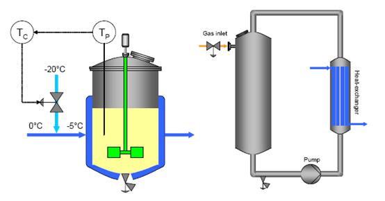
| + | The main equipment in multipurpose plants is the stirred tank reactor, which fulfils the flexibility requirements arising from the varied physical states of the materials being used (e.g. dry powders, wet solids, pastes, liquids, emulsions, gases). The vessels are required to withstand a range of process conditions (e. g. temperature, pressure, corrosion) and are thus usually made of stainless steel, rubber- or glass-lined steel, enamel coated, or other special materials. The mechanical design of the agitator baffles and cooling systems is constrained by the need to attach and maintain the rubber or glass lining. | ||
| − | + | Other characteristics: | |
| − | + | ::*used for both batch and continuous mode, as well as in cascades | |
| + | ::*sized up to 60 m3 (fermentation reactors up to about 1000 m3) | ||
| − | + | ::*usually dished bottom (reactions may be carried out under pressure) | |
| − | + | ::*equipped with one or more stirrers to ensure the requested mixing degree, heat-exchange performance, etc. | |
| + | ::*jackets or half pipe coils are often fitted around the vessel to provide heat transfer | ||
| − | + | ::*wall baffles are installed inside to prevent the gross rotation (“swirl”) of the contents with the stirrer. | |
| − | |||
| + | [[Image:Stirred tank reactor.jpg]] | ||
| − | + | Figure 2: Stirred tank reactor (conventional temperature control, left) and loop reactor (right), BREF on Organic Fine Chemicals, Aug. 2006 | |
| − | |||
| + | Other used reactor types are, e.g: | ||
| − | + | ::*loop reactors (closed loop or continuous loop) | |
| − | + | ::*bubble columns (closed loop or continuous loop) | |
| − | + | ::*pipe reactors | |
| + | ::*tubular reactors. | ||
| − | |||
| − | + | ;b) Energy supply | |
| + | Two main sources of energy are consumed on the typical site: | ||
| − | + | ::*steam | |
| − | + | ::*electricity. | |
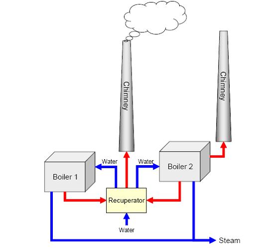
| + | Generally, only steam is produced on-site and electricity is supplied by an external source. Cogeneration by self-production of electricity and steam is advantageous on large sites. Energy is normally provided by boilers equipped with turbines fitted with burners for natural gas and fuel oil, with gas being the main fuel (about 95%). Spent solvents are often used as a fuel together with gas. Figure 3 shows an example for a setup with two boilers sharing an exhaust gas recuperator. Here the smaller boiler (boiler 1 which produces 80 tonnes steam/hour) is mainly used in summer and the larger boiler (boiler 2 which produces 160 tonnes steam/hour) mainly in winter, when the steam demand is higher. The recuperator cools down the exhaust gas from 130°C to about 45°C and warms the water from 20°C to about 60°C. About 3.8 MW heat is recovered. Steam and electricity can also be provided by on-site combined cycle power plants, thermal oxidisers or incinerators. | ||
| − | |||
| − | + | [[Image:Example of energy supply setup with two boilers.jpg]] | |
| + | |||
| + | Figure 3: Example of energy supply setup with two boilers, BREF on Organic Fine Chemicals, Aug. 2006 | ||
| + | |||
| + | |||
| + | ;c) Energy efficiency | ||
| + | |||
| + | ''1. Green chemistry:'' | ||
| + | Concerning the production of chemicals, the principle of green chemistry is to promote the use of alternative synthetic routes and alternative reaction conditions to existing less environmentally friendly processes; i.e. by minimising energy requirements, in recognition of the associated environmental and economic impacts. Reactions at ambient temperatures and pressures should be preferred | ||
| − | + | ''2. Enzymatic processes versus chemical processes'' | |
;Description | ;Description | ||
| − | + | Using enzymatic processes instead of chemical processes is advantageous from an environmental point of view. Less synthesis steps (no additional modification or protection of functional groups) and low solvent use are the major beneficial effects. Energy savings, fewer safety and disposal issues, and improved product quality also lead to cost benefits. The enzyme can be used in solution or fixed on a substrate, or as part of a polyfunctional enzymatic system, e.g. in living cells, free in a reaction medium or fixed on a substrate. | |
;Achieved environmental benefits | ;Achieved environmental benefits | ||
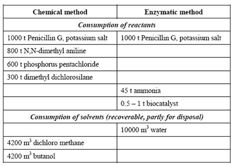
| − | + | An example from the manufacture of 6-aminopenicillanic acid is presented in the following table: | |
| + | |||
| + | |||
| + | Table 1: Comparison of enzymatic and chemical processes. Consumption levels for the conversion of 1000 t Penicillin G, BREF on Organic Fine Chemicals, Aug. 2006 | ||
| + | |||
| + | |||
| + | [[Image:Comparison of enzymatic and chemical processes.jpg]] | ||
;Cross-media effects | ;Cross-media effects | ||
| − | + | Higher water consumption. | |
;Operational data | ;Operational data | ||
| − | No | + | No information provided. |
;Applicability | ;Applicability | ||
| − | + | The technical feasibility has to be considered individually. | |
| + | |||
| + | |||
| + | Other examples with environmental advantages are [46, Ministerio de Medio Ambiente, 2003]: | ||
| + | |||
| + | ::*Aspartame | ||
| + | |||
| + | ::*7-amino cefalosporanic acid | ||
| + | |||
| + | ::*anticonvulsive LY300164. | ||
| + | |||
| + | Where API manufacture on a site requires the observance of the rules of current Good Manufacturing Practice (cGMP) or approval by the Federal Drug Administration (FDA), process modifications can be only carried out fulfilling the required variation procedure. This represents a serious obstacle for the redesign of existing processes. | ||
;Economics | ;Economics | ||
| − | + | Cost benefits. | |
;Driving force for implementation | ;Driving force for implementation | ||
| − | + | Cost benefits. | |
| − | + | ''3. Reactions in supercritical CO2'' | |
| − | + | ||
;Description | ;Description | ||
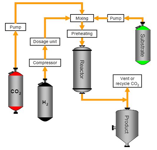
| − | + | Reactions can be carried out in supercritical CO2 (supercritical point at 73.8 bar/31°C) using a supercritical reactor system, as illustrated in the following figure for hydrogenations. Supercritical CO2 replaces the solvent and shows similar properties to n-hexane. The reaction is no longer mass transfer controlled and hydrogen shows infinite solubility. Reaction conditions such as pressure, temperature, residence time and hydrogen concentration can be manipulated independently. On completion, the CO2 is evaporated by reducing the pressure. | |
| − | + | [[Image:A supercritical reactor system.jpg]] | |
| + | |||
| + | Figure 4: A supercritical reactor system, BREF on Organic Fine Chemicals, Aug. 2006 | ||
| + | |||
| + | |||
| + | Achieved environmental benefits | ||
| + | |||
| + | ::*low/no VOCs | ||
| + | |||
| + | ::*less waste streams | ||
| + | |||
| + | ::*higher selectivity | ||
| − | + | ::*higher yields. | |
;Cross-media effects | ;Cross-media effects | ||
| − | + | None believed likely. | |
;Operational data | ;Operational data | ||
| − | + | Above 73.8 bar/31 °C. | |
;Applicability | ;Applicability | ||
| − | + | Some reaction types under development besides hydrogenation include: | |
| + | |||
| + | ::*alkylation | ||
| + | |||
| + | ::*acid catalysed reactions/etherifications | ||
| + | |||
| + | ::*hydroformylation. | ||
;Economics | ;Economics | ||
| − | + | Reactions in supercritical CO2 represent cost-intensive processes, but the costs are justified by selectivity, reduction of energy use, saving of costs for product workup and solvent disposal. | |
| − | ;Driving force for implementation | + | ;Driving force for implementation |
| − | + | Selectivity through an inherently “tunable” system. | |
| + | ''4. A “state of the art” multipurpose plant'' | ||
| − | + | Multipurpose plants enable the operator to manufacture different products with a certain flexibility according to market requirements. Figure 5 gives an impression of the arrangement in a typical plant, which uses gravity flow for efficient material transport. The main components in the multipurpose plant are: | |
| + | |||
| + | ::* raw material storage (warehouse, tank farm) | ||
| + | |||
| + | ::* reactors and vessels | ||
| + | |||
| + | ::* finished and intermediate storage | ||
| + | |||
| + | ::* utilities (e.g. cooling, vacuum, steam, cleaning) | ||
| + | |||
| + | ::* process control systems | ||
| + | |||
| + | ::* feed tanks (usually upper floors) | ||
| + | |||
| + | ::* purification and separation equipment | ||
| + | |||
| + | ::* recovery and abatement facilities | ||
| + | |||
| + | ::* blow-off systems and catch tanks. | ||
| + | |||
| + | Production campaigns with batch wise, semi-batch or continuous operation of reactors and facilities for product work-up alternate with shutdown, cleaning and start-up situations. | ||
| + | |||
| + | |||
| + | [[Image:Typical lay-out for a multipurpose plant.jpg]] | ||
| + | |||
| + | Figure 5: Typical lay-out for a multipurpose plant, BREF on Organic Fine Chemicals, Aug. 2006 | ||
| + | |||
| + | |||
| + | An example multi-purpose plant can have 22 different products/intermediate by utilizing 17 vessels in a production building. This picture could vary drastically over the year due to a possibly changed market situation. The use of the capacity varies from 60 to 95 %. Lower values would be critical from an economic point of view. Higher values would represent a real challenge from an operational point of view. | ||
;Description | ;Description | ||
| − | + | The new production site manufactures pharmaceuticals and performs reactions such as chiral synthesis, biocatalysis, Grignard reactions, Friedel-Crafts reactions, bromination, chlorination, aromatic substitutions, metal hydride reductions. | |
| + | |||
| + | |||
| + | Major aspects have been considered as follows: | ||
| + | |||
| + | ::* several techniques were considered to control VOC emissions, including: extra condensors, cryogenic condensation, scrubbing, thermal oxidation. The choice was made for thermal oxidation because all possible emissions on the site can be treated at once. Furthermore, the thermal oxidiser can be used as an energy provider for the plant | ||
| + | |||
| + | ::* the characteristic value for residue production is about 15 tonnes residue per tonne product. Products are made in quantities of up to 100 tonnes/year/product. Recycle loops are, in many cases, not possible due to quality and purity requirements. Only the solvents that are contaminated with, for example halogenated compounds or salts, are disposed of to a waste treatment plant | ||
| + | |||
| + | ::* a survey is being carried out to make processes more selective and, therefore, produce less sludge at the WWTP, as the sludge has to be processed abroad | ||
| + | |||
| + | ::* other measures to prevent residues include: using enzymes in the processes, performing reactions at lower temperatures, racemise after the reaction is completed | ||
| + | |||
| + | ::* there is one process with runaway hazard. The temperature is measured in the reactor during start off to check if the reaction is running according to the instructions. The reaction is quenched if the temperature rises above the alarm setpoint. | ||
| + | |||
| + | The plant is designed in such a way that diffuse emissions are minimised and that the energy efficiency is optimised: On the top floor (5th floor), starting materials can be weighed and loaded in closed rooms. Products fall into the reactors that hang on the 3rd floor, using gravity instead of pumps and/or vacuum. This prevents uncontrolled emissions to a large extent, since pumps are an important source of uncontrolled emissions, and can save energy. On the 4th floor (thus between weighing and reactors) hang (double) condensors using thermal oil as the cooling medium. Solvents can either be returned to the reactors or run to a reception vessel. All systems are closed to prevent uncontrolled emissions. On the lower floors, products fall from the reactors into vessels where reception and drying functions are combined. Here again gravity does the work instead of pumps/vacuum. On each floor, pipes gather to a manifold. Apparatus can be connected to each other in different configurations using flexible pipes, depending on the process steps needed, thus preventing the use of building materials. Packings are replaced when a production campaign is finished (i.e. when a switch is made to the synthesis of a different product) to make sure the system remains safe and no uncontrolled emissions occur. When the configuration of the equipment is adapted to the new process, the packings are changed and the equipment is set under pressure in order to detect potential leaks. Inside the reactor during production, a light overpressure of nitrogen slightly decreases the evaporation of VOCs (blanketing). The building is closed and ventilated mechanically. The pressure inside the building is 10% higher than outside. The building is divided into fireproof compartments which are individually ventilated. All emitted gases from these compartments are either recycled, or after waste heat recovery, released to the air. All condensors and vents from sewage are connected to the thermal oxidiser to make sure all point emissions are treated. Waste water vents are also connected to the thermal oxidiser. | ||
;Achieved environmental benefits | ;Achieved environmental benefits | ||
| − | + | ::* high energy efficiency | |
| + | |||
| + | ::* consequent minimisation of diffuse/fugitive emissions | ||
| + | |||
| + | ::* extended recovery and abatement of VOC emissions. | ||
;Cross-media effects | ;Cross-media effects | ||
| − | + | None believed likely. | |
;Operational data | ;Operational data | ||
| − | No | + | No information provided. |
;Applicability | ;Applicability | ||
| − | + | Generally applicable for new installations (including buildings). Technical restrictions may lead to individual solutions. For example the use of gravity flow is not applicable for high viscosity liquids. Alternatively to the use of gravity flow, canned pumps can be used to prevent fugitive emissions. | |
;Economics | ;Economics | ||
| − | + | Cost benefits can be presumed through higher efficiency. | |
;Driving force for implementation | ;Driving force for implementation | ||
| − | + | Cost and environmental benefits, and efficiency. | |
| − | ''Literature: BAT for | + | ''Literature: BAT for the Manufacture of Organic Fine Chemicals, August 2006'' |
Back to [[Subsection DG chemicals|EFFICIENCY FINDER FOR CHEMICAL INDUSTRY]] | Back to [[Subsection DG chemicals|EFFICIENCY FINDER FOR CHEMICAL INDUSTRY]] | ||
Latest revision as of 16:20, 14 February 2013
Back to EFFICIENCY FINDER FOR CHEMICAL INDUSTRY
Process engineering and energy issues for the production of Organic fine chemicals
- a) Reactors
The main equipment in multipurpose plants is the stirred tank reactor, which fulfils the flexibility requirements arising from the varied physical states of the materials being used (e.g. dry powders, wet solids, pastes, liquids, emulsions, gases). The vessels are required to withstand a range of process conditions (e. g. temperature, pressure, corrosion) and are thus usually made of stainless steel, rubber- or glass-lined steel, enamel coated, or other special materials. The mechanical design of the agitator baffles and cooling systems is constrained by the need to attach and maintain the rubber or glass lining.
Other characteristics:
- used for both batch and continuous mode, as well as in cascades
- sized up to 60 m3 (fermentation reactors up to about 1000 m3)
- usually dished bottom (reactions may be carried out under pressure)
- equipped with one or more stirrers to ensure the requested mixing degree, heat-exchange performance, etc.
- jackets or half pipe coils are often fitted around the vessel to provide heat transfer
- wall baffles are installed inside to prevent the gross rotation (“swirl”) of the contents with the stirrer.
Figure 2: Stirred tank reactor (conventional temperature control, left) and loop reactor (right), BREF on Organic Fine Chemicals, Aug. 2006
Other used reactor types are, e.g:
- loop reactors (closed loop or continuous loop)
- bubble columns (closed loop or continuous loop)
- pipe reactors
- tubular reactors.
- b) Energy supply
Two main sources of energy are consumed on the typical site:
- steam
- electricity.
Generally, only steam is produced on-site and electricity is supplied by an external source. Cogeneration by self-production of electricity and steam is advantageous on large sites. Energy is normally provided by boilers equipped with turbines fitted with burners for natural gas and fuel oil, with gas being the main fuel (about 95%). Spent solvents are often used as a fuel together with gas. Figure 3 shows an example for a setup with two boilers sharing an exhaust gas recuperator. Here the smaller boiler (boiler 1 which produces 80 tonnes steam/hour) is mainly used in summer and the larger boiler (boiler 2 which produces 160 tonnes steam/hour) mainly in winter, when the steam demand is higher. The recuperator cools down the exhaust gas from 130°C to about 45°C and warms the water from 20°C to about 60°C. About 3.8 MW heat is recovered. Steam and electricity can also be provided by on-site combined cycle power plants, thermal oxidisers or incinerators.
Figure 3: Example of energy supply setup with two boilers, BREF on Organic Fine Chemicals, Aug. 2006
- c) Energy efficiency
1. Green chemistry:
Concerning the production of chemicals, the principle of green chemistry is to promote the use of alternative synthetic routes and alternative reaction conditions to existing less environmentally friendly processes; i.e. by minimising energy requirements, in recognition of the associated environmental and economic impacts. Reactions at ambient temperatures and pressures should be preferred
2. Enzymatic processes versus chemical processes
- Description
Using enzymatic processes instead of chemical processes is advantageous from an environmental point of view. Less synthesis steps (no additional modification or protection of functional groups) and low solvent use are the major beneficial effects. Energy savings, fewer safety and disposal issues, and improved product quality also lead to cost benefits. The enzyme can be used in solution or fixed on a substrate, or as part of a polyfunctional enzymatic system, e.g. in living cells, free in a reaction medium or fixed on a substrate.
- Achieved environmental benefits
An example from the manufacture of 6-aminopenicillanic acid is presented in the following table:
Table 1: Comparison of enzymatic and chemical processes. Consumption levels for the conversion of 1000 t Penicillin G, BREF on Organic Fine Chemicals, Aug. 2006
- Cross-media effects
Higher water consumption.
- Operational data
No information provided.
- Applicability
The technical feasibility has to be considered individually.
Other examples with environmental advantages are [46, Ministerio de Medio Ambiente, 2003]:
- Aspartame
- 7-amino cefalosporanic acid
- anticonvulsive LY300164.
Where API manufacture on a site requires the observance of the rules of current Good Manufacturing Practice (cGMP) or approval by the Federal Drug Administration (FDA), process modifications can be only carried out fulfilling the required variation procedure. This represents a serious obstacle for the redesign of existing processes.
- Economics
Cost benefits.
- Driving force for implementation
Cost benefits.
3. Reactions in supercritical CO2
- Description
Reactions can be carried out in supercritical CO2 (supercritical point at 73.8 bar/31°C) using a supercritical reactor system, as illustrated in the following figure for hydrogenations. Supercritical CO2 replaces the solvent and shows similar properties to n-hexane. The reaction is no longer mass transfer controlled and hydrogen shows infinite solubility. Reaction conditions such as pressure, temperature, residence time and hydrogen concentration can be manipulated independently. On completion, the CO2 is evaporated by reducing the pressure.
Figure 4: A supercritical reactor system, BREF on Organic Fine Chemicals, Aug. 2006
Achieved environmental benefits
- low/no VOCs
- less waste streams
- higher selectivity
- higher yields.
- Cross-media effects
None believed likely.
- Operational data
Above 73.8 bar/31 °C.
- Applicability
Some reaction types under development besides hydrogenation include:
- alkylation
- acid catalysed reactions/etherifications
- hydroformylation.
- Economics
Reactions in supercritical CO2 represent cost-intensive processes, but the costs are justified by selectivity, reduction of energy use, saving of costs for product workup and solvent disposal.
- Driving force for implementation
Selectivity through an inherently “tunable” system.
4. A “state of the art” multipurpose plant
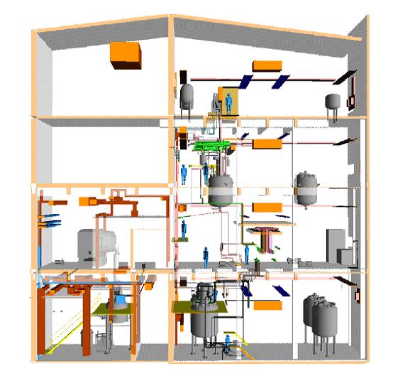
Multipurpose plants enable the operator to manufacture different products with a certain flexibility according to market requirements. Figure 5 gives an impression of the arrangement in a typical plant, which uses gravity flow for efficient material transport. The main components in the multipurpose plant are:
- raw material storage (warehouse, tank farm)
- reactors and vessels
- finished and intermediate storage
- utilities (e.g. cooling, vacuum, steam, cleaning)
- process control systems
- feed tanks (usually upper floors)
- purification and separation equipment
- recovery and abatement facilities
- blow-off systems and catch tanks.
Production campaigns with batch wise, semi-batch or continuous operation of reactors and facilities for product work-up alternate with shutdown, cleaning and start-up situations.
Figure 5: Typical lay-out for a multipurpose plant, BREF on Organic Fine Chemicals, Aug. 2006
An example multi-purpose plant can have 22 different products/intermediate by utilizing 17 vessels in a production building. This picture could vary drastically over the year due to a possibly changed market situation. The use of the capacity varies from 60 to 95 %. Lower values would be critical from an economic point of view. Higher values would represent a real challenge from an operational point of view.
- Description
The new production site manufactures pharmaceuticals and performs reactions such as chiral synthesis, biocatalysis, Grignard reactions, Friedel-Crafts reactions, bromination, chlorination, aromatic substitutions, metal hydride reductions.
Major aspects have been considered as follows:
- several techniques were considered to control VOC emissions, including: extra condensors, cryogenic condensation, scrubbing, thermal oxidation. The choice was made for thermal oxidation because all possible emissions on the site can be treated at once. Furthermore, the thermal oxidiser can be used as an energy provider for the plant
- the characteristic value for residue production is about 15 tonnes residue per tonne product. Products are made in quantities of up to 100 tonnes/year/product. Recycle loops are, in many cases, not possible due to quality and purity requirements. Only the solvents that are contaminated with, for example halogenated compounds or salts, are disposed of to a waste treatment plant
- a survey is being carried out to make processes more selective and, therefore, produce less sludge at the WWTP, as the sludge has to be processed abroad
- other measures to prevent residues include: using enzymes in the processes, performing reactions at lower temperatures, racemise after the reaction is completed
- there is one process with runaway hazard. The temperature is measured in the reactor during start off to check if the reaction is running according to the instructions. The reaction is quenched if the temperature rises above the alarm setpoint.
The plant is designed in such a way that diffuse emissions are minimised and that the energy efficiency is optimised: On the top floor (5th floor), starting materials can be weighed and loaded in closed rooms. Products fall into the reactors that hang on the 3rd floor, using gravity instead of pumps and/or vacuum. This prevents uncontrolled emissions to a large extent, since pumps are an important source of uncontrolled emissions, and can save energy. On the 4th floor (thus between weighing and reactors) hang (double) condensors using thermal oil as the cooling medium. Solvents can either be returned to the reactors or run to a reception vessel. All systems are closed to prevent uncontrolled emissions. On the lower floors, products fall from the reactors into vessels where reception and drying functions are combined. Here again gravity does the work instead of pumps/vacuum. On each floor, pipes gather to a manifold. Apparatus can be connected to each other in different configurations using flexible pipes, depending on the process steps needed, thus preventing the use of building materials. Packings are replaced when a production campaign is finished (i.e. when a switch is made to the synthesis of a different product) to make sure the system remains safe and no uncontrolled emissions occur. When the configuration of the equipment is adapted to the new process, the packings are changed and the equipment is set under pressure in order to detect potential leaks. Inside the reactor during production, a light overpressure of nitrogen slightly decreases the evaporation of VOCs (blanketing). The building is closed and ventilated mechanically. The pressure inside the building is 10% higher than outside. The building is divided into fireproof compartments which are individually ventilated. All emitted gases from these compartments are either recycled, or after waste heat recovery, released to the air. All condensors and vents from sewage are connected to the thermal oxidiser to make sure all point emissions are treated. Waste water vents are also connected to the thermal oxidiser.
- Achieved environmental benefits
- high energy efficiency
- consequent minimisation of diffuse/fugitive emissions
- extended recovery and abatement of VOC emissions.
- Cross-media effects
None believed likely.
- Operational data
No information provided.
- Applicability
Generally applicable for new installations (including buildings). Technical restrictions may lead to individual solutions. For example the use of gravity flow is not applicable for high viscosity liquids. Alternatively to the use of gravity flow, canned pumps can be used to prevent fugitive emissions.
- Economics
Cost benefits can be presumed through higher efficiency.
- Driving force for implementation
Cost and environmental benefits, and efficiency.
Literature: BAT for the Manufacture of Organic Fine Chemicals, August 2006
