Heating of carbon black
Back to Subsection DG chemicals
Production processes
A summary of the most important production processes is given in Table 1. In general, the processes are divided into two groups: those employing incomplete or partial combustion and those based on thermal cracking (pyrolysis) [47, InfoMil, 2002]. This nomenclature is somewhat misleading insofar as the carbon black resulting from the partial combustion process is also formed by pyrolysis. The two types of processes differ in that, in the partial combustion processes, air is used to burn part of the feedstock, thus producing the energy required to carry out the pyrolysis, whereas in the thermal cracking process, heat is generated externally and introduced into the process.
Table 1: Manufacturing processes and feedstock used for the production of carbon black [47, InfoMil, 2002]
The furnace black process is currently the most important production process. It accounts for
more than 95 % of the total worldwide production [47, InfoMil, 2002]. The advantages of the
furnace black process are its great flexibility, which allows the manufacture of various grades of
carbon black, and its better economy compared to other processes. The following comparison
makes this apparent: for similar grades of carbon black, the production rate of one flame is
approximately 0.002 kg/h for channel black, approximately 0.2 kg/h for gas black, and
approximately 2000 kg/h for a modern furnace black reactor. Some furnace black reactors have
production rates of up to 5000 kg/h.
However, in spite of the more advantageous furnace black process, the production processes listed in Table 1(except for the channel black process that is no longer operated) are still in use for the production of special carbon blacks which cannot be obtained via the furnace black process.
Furnace black process
In the last few decades, the rapidly expanding automobile industry required increasing numbers of tyres with various characteristics. This led not only to the development of new rubber grades, but also to the development of new carbon blacks required by the increasingly refined application processes and to the development of a new and better manufacturing process, the furnace black process. Unlike the old channel black process, this process allows the production of virtually all grades of carbon black required by the rubber industry.
The furnace black process was developed in the United States in the 1920s and since then, it has been greatly refined. In the late 1930s it was developed as a truly continuous process, carried out in closed reactors, so that all inputs can be carefully controlled.
The heart of a furnace black plant is the furnace in which the carbon black is formed. The primary feedstock is injected, usually as an atomised spray, into a high temperature zone of high energy density, which is achieved by burning a secondary feedstock (natural gas or oil) with air.
The oxygen, which is in excess with respect to the secondary feedstock, is not sufficient for complete combustion of the primary feedstock, the majority of which is, therefore, pyrolysed to form carbon black at 1200 – 1900 °C.
The reaction mixture is then quenched with water and further cooled in heat exchangers, and the carbon black is collected from the tail-gas by a filter system.
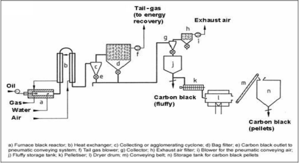
Figure 1 shows a schematic drawing of a furnace black production plant.
Figure 1: Furnace black process [47, InfoMil, 2002]
The primary feedstock, preferably petrochemical or carbo-chemical heavy aromatic oils, some
of which begin to crystallise near ambient temperature, is stored in open to air, vented and
heated tanks equipped with circulation pumps to maintain a homogeneous mixture. The primary
feedstock is pumped to the reactor via heated and/or insulated pipes to a heat exchanger, where
it is heated to 150 - 250 °C to obtain a viscosity appropriate for atomisation. Various types of
spraying devices are used to introduce the primary feedstock into the reaction zone.
As the carbon black structure can be influenced by the presence of alkali metal ions in the reaction zone, alkali metal salts, preferably aqueous solutions of potassium salts (e.g. potassium carbonate, hydroxide or chloride), are often added to the oil in the oil injector. Alternatively, the additives may be sprayed separately into the combustion chamber. In special cases, other additives, e.g. alkaline-earth metal compounds, which increase the specific surface area, are introduced in a similar manner.
The energy to break C-H bonds is supplied by feedstock, which provides the reaction temperature required for the specific grades. Natural gas, petrochemical oils and other gases, e.g. coke oven gas or vaporised liquid petroleum gas may be used as secondary feedstock. Depending on the type of secondary feedstock, special burners are also used to obtain fast and complete combustion. The required air is preheated in heat exchangers by the hot carbon black containing gases leaving the reactor. This saves energy and thus improves the carbon black yield. Preheated air temperatures of 500 – 700 ºC are common.
The state-of-the-art carbon black plants install several production lines (or units) from the single high performance reactor to the silo for the final product, with throughputs as high as 20000 tonnes per year per line or higher. Present design optimises the quality, the yield and the operation of each plant.
The reactors of modern furnace black plants vary considerably in internal geometry, flow characteristics, and the manner in which fuel and feedstock are introduced. Nevertheless, they all have the same basic process steps in common: producing hot combustion gases in a combustion chamber, injecting the feedstock and rapidly mixing it with the combustion gases, vaporising the oil, pyrolysing it in the reaction zone, and rapidly cooling the reaction mixture in the quenching zone to temperatures of 500 – 800 °C.
All reactors have a gas-tight metal jacket. The reaction zone is coated with a ceramic inner liner, generally on an alumina base, which is stable to temperatures of approx. 1800 °C. Several quenching positions allow the effective reaction volume of the reactor to be adjusted. This allows variation of the mean residence time of the carbon black at the high reaction temperature. Typical residence times for reinforcing blacks are 10 – 100 ms.
Most furnace black reactors are arranged horizontally. Some vertical reactors are used especially for the manufacture of certain semi-reinforcing blacks.
The properties of carbon blacks depend on the ratios of primary feedstock, secondary feedstock and air, which therefore must be carefully controlled. The particle size of the carbon black generally decreases with increasing amounts of excess air relative to the amount needed for the complete combustion of the secondary feedstock. Since the excess air reacts with the primary feedstock, a greater amount of air leads to higher oil combustion rates, resulting in rising temperatures in the reaction zone. As a consequence, the nucleation velocity and the number of particles formed increase, but the mass of each particle and the total yield decrease. The yields, which depend on the carbon black type and the type of primary feedstock, range between 40 and 65 % for some types of carbon black [47, InfoMil, 2002]. High surface area pigment blacks with markedly smaller particle size than rubber blacks give lower yields (10 - 30 %). Other parameters influencing carbon black quality are the manner in which the oil is injected, atomised, and mixed with the combustion gases, the type and amount of additives, the preheating temperature of the air and the quench position.
As long as the carbon black is in contact with the surrounding gases at the high reaction temperature, several reactions on the carbon surface occur (e.g. Boudouard reaction, water gas reaction), so that the chemical nature of the carbon black surface is modified with increasing residence time. When quenched to temperatures below 900 °C, these reactions are stopped and a certain state of surface activity is frozen. Varying the pelletising and drying conditions (see below) can also further modify carbon black surface properties.
The total mass put through a reactor can vary between 2 and 25 t/h. Although this is done at high streaming velocities (up to 800 m/s) and high temperatures (up to 1800 °C), modern high performance refractory lining can have lifetimes of two years and more. The metal reactor jackets last much longer. Because of the reducing atmosphere and the high temperatures in the reactor, the tail-gas, which consists of 30 – 50 vol-% water vapour, 30 – 50 vol-% nitrogen, and 1 - 5 vol-% carbon dioxide, also contains a certain amount of combustible gases, such as carbon monoxide and hydrogen.
Furthermore, traces of sulphur compounds (H2S, CS2 and COS) and nitrogen compounds (HCN, NOX, NH3) are present in these gases. The amount of these compounds depends on the composition of the feedstock and the processing conditions. The combustible gases normally include 6 – 12 vol-% carbon monoxide, 6.5 – 14 vol-% hydrogen, small amounts of methane and other hydrocarbons. The lower heating value lies between 1.7 and 3.8 MJ/m3. The gas is normally burned for environmental reasons, and a portion of its energy is used, e.g. for heating dryer drums and for the production of steam and/or electricity. At many plants, the remaining portion of the tail-gas is combusted using a flare.
The mixture of gas and carbon black leaving the reactor is cooled to 250 – 350 °C in heat exchangers by counter-flowing combustion air and then conducted into the collecting system. Formerly, a combination of electro-flocculators and cyclones or cyclones and filters were used. Currently, simpler units are preferred. Generally, the collecting system consists of only one high performance bag filter with several chambers, which are periodically purged by counter-flowing filtered gas or by pulse-jets. Occasionally, an agglomeration cyclone is installed between the heat exchanger and the filter.
Depending on the capacity of the production unit, the filter may contain several hundred bags with a total filter area of several thousand square metres. Usual filter loads are in the order of 0.2 – 0.4 m3.m-2.min-1.
Since the filtered gas contains approx. 30 - 50 vol-% water vapour, most filters operate at temperatures above 200 °C to avoid condensation. The residual carbon black content in the filtered tail-gas is less than 100 mg/m3 in western countries. The fluffy carbon black coming out of the filter is pneumatically conveyed into a first storage tank. Small amounts of solid impurities (‘grit,’ e.g. iron, rust, or coke particles) are either removed by magnets and classifiers or milled to an appropriate consistency.
Fluffy carbon black has an extremely low bulk density of 20 – 60 g/l. To facilitate handling and further processing by the customer, it must be compacted. Densification by ‘outgassing’ – a process by which the carbon black is passed over porous, evacuated drums – is the weakest form of compacting and allows the carbon black to retain its powdery state. This form of compacting is used for certain pigment blacks, which must retain easy dispersibility. Other pigment blacks and rubber blacks are compacted by pelletisation. Two processes are used: dry and wet pelletisation.
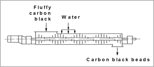
Dry pelletisation is a simple and energy saving method, but it does not work with all types of carbon black. It is mainly used for pigment black. Dry pelletisation is carried out in rotating drums, where the powdery carbon black rolls to form small spheres. The wet pelletisation process is used for the majority of rubber blacks. Carbon black, water, and small amounts of additives (e.g. molasses, ligninosulphonates) are mixed in special pelletisers. They usually consist of a horizontal cylinder approx. 3 m long and 0.7 – 1 m in diameter, in the axis of which a pin shaft rotates at 300 – 750 rpm. The pelleting machine used in the wet pelletisation process is presented in Figure 2.
Figure 2: Pelleting machine used in the wet pelletisation process [47, InfoMil, 2002]
During the wet pelletisation process, the water containing the pelletising agents dissolved in it,
is injected via spray nozzles. The density of the pelletised material is approx. 10 times that of
the original carbon black. The pellet crush strength and some application properties in rubber
can be influenced by the type and amount of the pelletising agent. The size of the pellets is
approx. 1 – 2 mm. The carbon black leaving the pelletising machine contains approximately
50 wt-% water. It is dried in dryer drums by a variety of means.
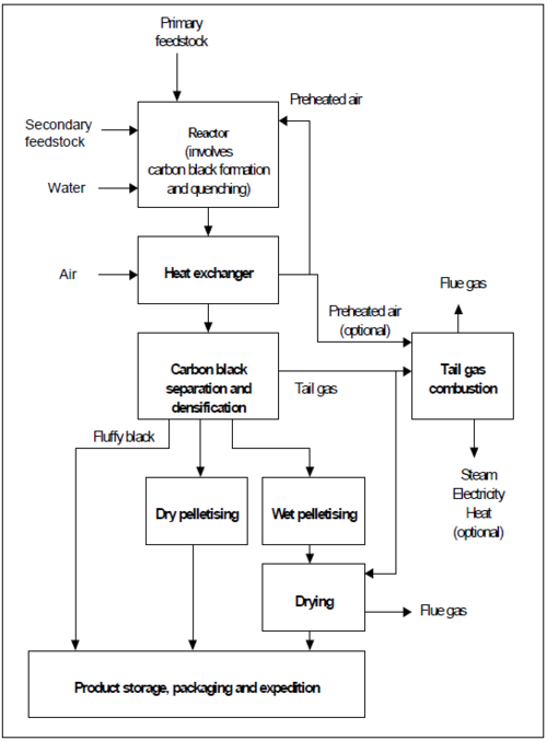
The most common method is indirect heating by combusting tail-gas. Drying temperatures, generally between 150 and 250 °C, allow further modification of the carbon black properties. The dried carbon black is transported via conveyor belts and elevators to the storage tank or packing station. Bulk densities of wet-pelletised carbon blacks are between 250 and 550 g/l. A flow diagram illustrating the complete furnace black process is shown in Figure 3.
Figure 3: Example of possible configuration of the furnace black process [47, InfoMil, 2002]
Energy consumption
It is difficult to make an accurate energy balance for the furnace black process in general, due to the following reasons:
- it is unknown exactly which part of the feedstock is converted into product carbon black
- energy recovery for internal and external use takes place in different forms (e.g. electricity
and steam). Sometimes, the tail-gas is even sold as such. Nearly all carbon black plants reuse a substantial part (15 to 30 %) of the tail-gas in their dryers. However, for combustion of the rest of the tail-gas, numerous configurations of controlled thermal combustors, boilers, combined heat and power (CHP) installations [86, The Council of the EU, 2004] and/or flares are used [47, InfoMil, 2002]
- feedstock and operating conditions are changed frequently, in order to produce different
carbon black grades. Therefore, the energy content of the feedstock and the flow and calorific value of the tail-gas varies. In addition, energy losses occur during start-ups and shut-downs.
Table 1 shows the typical total electrical energy consumption for rubber black plants (assumed yield 50 % for rubber black).
Table 1: Typical total electrical energy consumption for rubber black plants [47, InfoMil, 2002]
A rough energy balance for a rubber black furnace black plant is shown below in Table 2.
As can be seen in Table 2 above, the main incoming energy carriers in the furnace are: (1) the primary feedstock, (2) the secondary feedstock and (3) the electricity. The main outgoing energy flows can be categorised into: (4) product, (5) tail-gas and (6) other (e.g. heat loss through flue-gases, cooling water, radiation, etc.).
Most plants use part of the generated tail-gas for heating the dryers of the wet pelletising process. The amount of this tail-gas varies between 15 and 35 % of tail-gas production, depending on the fuel requirements of the dryer. Many plants in Western Europe exploit the remaining tail-gas for the generation of steam and (in some locations) electricity. The potential recovery from the remaining tail-gas for a combined heat and power plant (CHP) at 80 % overall efficiency is between 9 and 26 GJ/tonne CB. Part of the produced steam (and electricity) can be used at several places in the process, but in general, plants that recover the total heat content of the tail-gas are net producers of energy and would benefit from an outside consumer [47, InfoMil, 2002].
Channel black and gas black processes
The channel black process, which had been used in the United States since the late 1800s, was the oldest process for producing small particle size carbon blacks on an industrial scale. Originally, this process also produced the first reinforcing blacks. In 1961, world production of channel black was about 120 kt. Due to low profitability and environmental difficulties, the last production plant in the United States was closed in 1976. Natural gas was used as the feedstock. The carbon black yield was only 3 – 6 %.
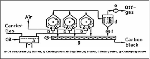
The gas black process was developed in the 1930s, in Germany, where natural gas was not available in sufficient amounts. It is similar to the channel black process, but uses coal tar oils instead of natural gas. Yields and production rates are much higher with oil-based feedstock; this process is still used to manufacture high quality pigment blacks with properties comparable to those of channel blacks. The gas black process has been used on an industrial scale since 1935. In the gas black process, illustrated in Figure 4, the feedstock is partially vaporised.
Figure 4: The gas black process [47, InfoMil, 2002]
The residual oil is continuously withdrawn. The oil vapour is transported to the production
apparatus by a combustible carrier gas (e.g. hydrogen, coke oven gas, or methane). Air may be
added to the oil-gas mixture for the manufacture of very small particle size carbon black.
Although this process is not as flexible as the furnace black process, various grades of gas black
can be made by varying the relative amounts of carrier gas, oil and air. The type of burners used
also influences the carbon black properties.
A gas black apparatus consists of a burner pipe approximately 5 m long, which carries 30 - 50 diffusion burners. The flames burn in contact with a water-cooled drum, where about half of the carbon black formed is deposited. This black is continuously scraped off and transported by a screw to a pneumatic conveying system. The gas black apparatus is surrounded by a steel housing open at the bottom. At the top, fans extract the off-gas into filters, which collect the carbon black suspended in the gas. Valves in the exhaust pipes can regulate the amount of air entering the apparatus. Several gas black apparatus are combined to form one production unit. One oil vaporiser feeds the whole unit. The production rate and the yield of an apparatus depend on the grade of carbon black produced. For a typical reinforcing black, the production rate is 7 - 9 kg/h and the yield is 60 %. The yield for high quality pigment blacks is considerably lower (10 – 30 %).
To remove possible impurities, the gas black is classified and then densified, pelletised, or submitted to an oxidative treatment (see Section 4.2.4). Such an increased surface oxidation improves the properties of the carbon black [47, InfoMil, 2002]
Lamp black process
The lamp black process is the oldest industrial scale production process. Currently, only a few plants still produce rather coarse blacks (with a mean particle diameter of approx. 100 nm) with special properties. They are used as non-reinforcing or semi-reinforcing blacks in rubber goods and as tinting black with a low pigment separation tendency.
The lamp black process is only partially continuous. The feedstock – oil with a high aromatic hydrocarbon content – is burned in flat steel vessels up to 1.5 m in diameter. The oil is continuously introduced into the vessel to keep a constant feedstock level. The off-gas containing carbon black is sucked into a conical exhaust pipe, which is coated with a ceramic inner liner and leads to the cooling and collecting system. The properties of carbon black can be influenced to some extent by variation of the distance between the vessel and the exhaust and the amount of air sucked into the apparatus. One lamp black apparatus can produce 100 kg/h carbon black. The production process must be interrupted at certain time intervals to remove residues containing coke from the vessels.
Thermal black process
Some special processes for producing carbon black are based on the thermal decomposition of lower gaseous hydrocarbons or atomised petroleum oils in the absence of air. The thermal black process, which was developed in the 1930s, is still used for the production of coarse carbon blacks (non-reinforcing carbon blacks) for special applications in the rubber industry. Contrary to the processes described above, energy generation and the pyrolysis reaction are not carried out simultaneously.
A thermal black plant consists of two furnaces, which are used in alternate heating and production periods of approx. 5 min duration – see Figure 5 below.
Figure 5: Thermal black process [47, InfoMil, 2002]
Each of the cylindrical furnaces (4 m in diameter and 6 m high) contains a network of
heat-resistant bricks. They are heated with natural gas or oil and air. At a temperature of approx.
1400 ºC, the air is switched off and only feedstock is introduced for pyrolysis. Since this
reaction is endothermic, the temperature falls. At about 900 °C, a new heating period is
necessary.
The output from the furnace, carbon black and nearly pure hydrogen, are cooled by injecting water into an ascending channel. The carbon black is separated in the collecting system. Diluting the natural gas with recycled hydrogen can produce carbon blacks of lower particle size. Fine thermal blacks (FT blacks) with mean primary particle sizes of 120 – 200 nm were manufactured in this way in the past, but their production has now been discontinued. Medium thermal blacks (MT blacks) with mean particle sizes of 300 – 500 nm are still produced and are obtained by using undiluted feedstock. The yield of MT blacks is approximately 40 % with respect to the total amount of feedstock used.
Thermal blacks are used in mechanical rubber goods often based on synthetic polymers. e.g. fluoro elastomers, which are designed for specialised application. At present, thermal blacks donate specific physical properties to the end-product, e.g. resistance to compression or permanent deformation, at levels which cannot be attained using standard furnace grade.
Acetylene black process
Acetylene and mixtures of acetylene with light hydrocarbons are the raw materials for a process that has been used since the early 1900s. Unlike other hydrocarbons, the decomposition of acetylene is highly exothermic.
The discontinuous explosion process, which was mainly used for the production of colour blacks, is the oldest technical process. Continuous processes were later developed with production rates of up to 500 kg/h. Acetylene or gases containing acetylene are fed into a preheated, cylindrical reactor with a ceramic inner liner. Once ignited, the decomposition heat that is evolved maintains the reaction.
The carbon black is collected in settling chambers and cyclones. Approximately 95 – 99 % of the theoretical yield is obtained.
The primary particles of acetylene black have different shapes than those of other carbon blacks. Because of their relatively high price, the application of acetylene blacks is limited to special uses, e.g. in dry cells. Total worldwide production is approx. 40 kt per year.
Other manufacturing processes
In a plasma, hydrocarbon vapours may be almost quantitatively decomposed into carbon and hydrogen. Many producers of carbon black have carried out research in this field. According to numerous patent specifications, this method can be used to make small particle carbon blacks with new properties. The electric arc process was the only large scale process using plasma reactions in which large quantities of carbon black were produced as a by-product of the production of acetylene. The particles of the arc carbon black resemble those of acetylene black. The mean primary particle size is approx. 35 nm. Today, this kind of carbon black is no longer used as a pigment. For information on the plasma process, refer to Section 9.4.
Since the price of feedstock, and thus, the profitability of the carbon black production processes, is highly dependent on the petrochemical industry, several attempts have been made to find new raw materials. Processes for obtaining carbon black directly from coal or for isolating carbon black from used tyres, for example, have been studied. None of them, however, has been of any commercial importance up until now. On the other hand, clay, milled coal, and coke have found limited use as substitutes for very coarse carbon blacks, primarily thermal blacks and some semi-reinforced blacks. The increasing use of precipitated silica in tyres and mechanical rubber goods, mostly in combination with organosilane coupling agents, which originally was indicative of an increasing search for new non-oil-based fillers, has led to new rubber properties
Source: European Commission, Large Volume Inorganic Chemicals - Solids and Others industry, August 2007, p. 208-215
Back to Subsection DG chemicals


